Toll free 800-227-7642 • Ph. 215-943-2930 • Fax 215-943-2931 • E-mail sales@sgfrantz.com


Model LB-1 Page 3
Diamagnetic Separation/Barrier Separation/ Paramagnetic Separation/Applications/
Field Graph/ L1 to LB1 Conversion/Feed Troughs/Feed Hopper/Complete System/Specifications

Conversion of Isodynamics to Barrier  Separators.

  The Barrier inventions carry forward a branch of magnetic separation technology which began with inventions by Samuel G. Frantz, the founder of the Company. The Frantz Isodynamic Separator, embodying these inventions, became the leading device for separation according to magnetic susceptibility. The inventions are widely acknowledged to have provided the key to selective separation.3

  The Frantz Isodynamic Separator has a virtually unlimited useful life. The elements of the Magnetic Barrier Laboratory Separator were consequently designed so that all parts can be installed in the base and the magnetic circuit of any Isodynamic Separator to convert it to a Barrier. (The first prototype of the Isodynamic Separator, manufactured in 1935 by Frantz, was in service at Bryn Mawr College in 1989, when it was converted to a Barrier.) The Bundesanstalt für Geowissenschaft und Rohstoffe of Hannover, Germany, converted one Isodynamic Separator to a Barrier in 1988, three more in 1989, and three more again in 1990.

3. U.S. Patent No. 2,056,426, issued October 6, 1936, to Samuel G. Frantz, assigned to S. G. Frantz Co. A recent paper by Gerhold, J., POTENTIAL OF A DRY ROTATING-DISK MAGNETIC SEPARATOR, Magnetic and Electrical Separation, Vol. 3, No. 4, June, 1992; pp. 241-258 (at p. 241 and footnote 1, p. 257) cites the patent as the reference for the statement “The key to truly selective separation has been known for several decades.

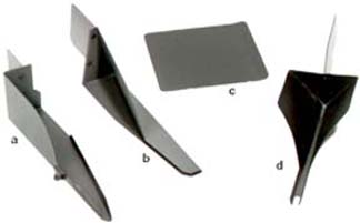
Figure 4.: Photograph of Standard Parts

Above photo features all standard parts for guiding particles into the Barrier field:

  • (a) Diamagnetic feed trough
  • (b) Steep side slope feed trough
  • (c) Feed blade
  • (d) Feed trough assembly

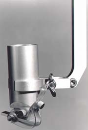
Figure 5: The hopper has an orifice one quarter inch in diameter above an adjustableplatform. Material piling up on the platform stops flow out of the hopper until vibration is supplied.
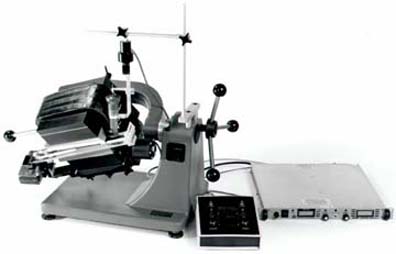
The Frantz® Magnetic Barrier Laboratory Separator, Model LB-1 (Complete System).
Specifications
for fig. 6
Electrical power required:
110-120V .a.c.,
3.0 A., 50-60 Hertz.

Size:
16 x 32 x 34" high
(41 x 81 x 86 cm)

Approx. Net weight: 329 lbs (150 kg)

Approx. Shipping weight: 555 lbs
(252 kg)

Shipped in 3 wood cases + 1 carton

Figure 6: The Barrier feed and travel systems have overcome difficulties often experienced with the Isodynamic Separator, such as clogging of the feed mechanism and erratic movement of particles.

The feed system is mounted on the column of the base. The feed hopper is suspended over the receiving compartment of the chute.

The feed and travel systems have separate electrical circuits and controls. The chute is supported on a sturdy, movable carriage to which the chute vibrator is attached at an attitude which transmits vibration at an angle upward from the surface of the chute.

The power supply, installed between the alternating current source and the separator’s coils, provides linked regulation of direct current and voltage. As resistance increases with heating of the coils, voltage increases automatically to maintain the selected current.

 In normal intermittent operation stable currents up to about 1.8 Amperes can be maintained in ambient temperature up to approximately 32º C (90º F).

With the former electrical system, without current regulation, maximum current at start-up of 1.8 A fell off to 1.5 A within one half-hour.


Go to previous page

Back to top

Go to next Model, L-1
Or Go back to Table of Contents for Laboratory Separators