|
|||||||||||||||||||||
|
|
||||||||||||||||||||
|
The magnetic field in the working space of the separator with no current flowing, which results from residual magnetization of its circuit, is high enough to cause ferromagnetic materials to agglomerate and stick in the chute. Reversing the direction of the current serves to eliminate residual magnetization. By a series of current reversals a minor hysteresis loop is established and stabilized, so that the direction and strength of the current which results in a zero field condition in the working space of the separator may be recorded and repeated. Low field strengths in the 0-1000 Gauss range can then be selected and any selected field intensity can be repeated. 
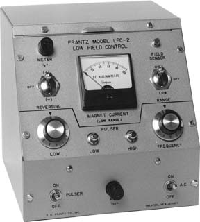
Current can be pulsed between selected high and low values at selected frequencies in a range from about 3 to 35 Hertz. When current is pulsed through the zero field value, polarization of ferromagnetic particles reverses with each pulse, causing trees of ferromagnetic particles to collapse and release entrained particles. As with paramagnetic and diamagnetic materials the magnetic properties of some ferromagnetic materials are too closely alike for separation by magnetic means. With the Low Field Control, however, the separator becomes highly sensitive to small differences in magnetic properties. The model LFC-2 is 8 inches high, 8-1/16 inches wide and 7-15/16 inches deep. A 0-100 milliampere meter is mounted on its sloping control panel. A pilot light on the panel is connected to a reed switch attached to the magnet poles, which opens when the field approaches zero. The diagram on the right shows a stabilized minor hysteresis loop for the magnetic circuit which serves the Isodynamic and the Magnetic Barrier Laboratory Separators. Field strength is measured between plus and minus seventy milliamperes. The width of the loop is significant for low intensity fields. In this stabilized loop the field in the gap of the separator is about 1,100 Gauss at plus 70 mA (point A) and about minus 1,000 Gauss at minus 70 mA (point E). As current is reduced from plus 70 mA, the field declines to about 100 Gauss at zero mA (point B), but does not reach zero Gauss until, after direction is reversed, current is increased to about minus eight mA (point C). If current is pulsed on the negative side of the loop between, say, zero and minus 40 mA, the field pulses between a maximum value of about minus 500 Gauss (point D), through zero, to somewhere between plus 50 and 100 Gauss, the value of the residual field with no applied current. As the direction of the field changes from minus, under applied current, to plus, the direction of the residual field, polarization of ferromagnetic particles reverses direction, causing “trees” of agglomerated particles to collapse. The collapse of trees is visible at lower pulse frequencies. |
|||||||||||||||||||||